Introduction:
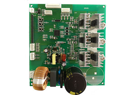
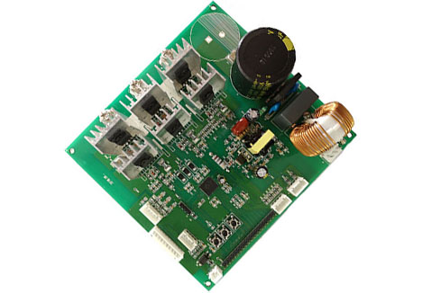
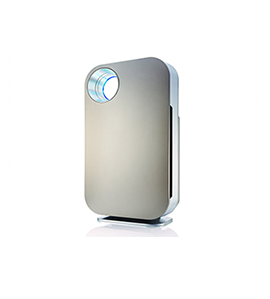
Active Semi M0 Cortex SoC: PAC5250 is used in this high voltage three-phase brushless DC motor control board. The chip integrates digital core, analog core and AC/DC power management core. The three cores are all integrated into one chip, so the system has simple structure, fewer devices, high reliability and high cost performance. At the same time, software packages and PC software are provided to facilitate the configuration of motor parameters, allowing developers to run the motor in one day and verify the system in seven days.
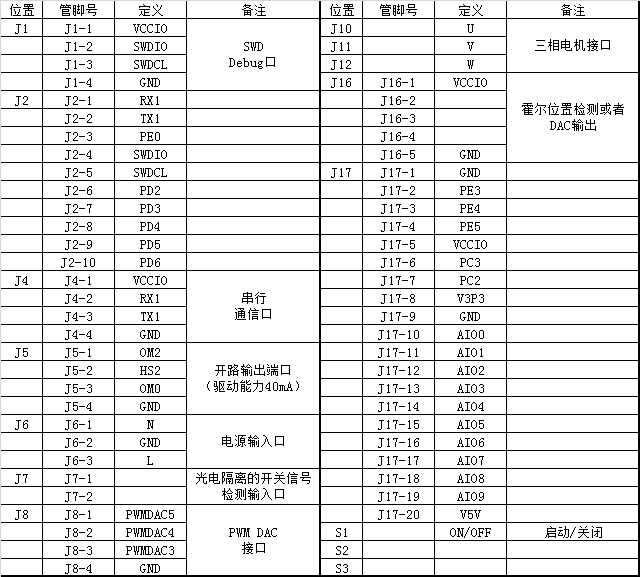
In order to expand conveniently, a series of pins are installed on the control board to measure each pin signal of the main chip, including 14 PWM output channels, 9 ADC input channels, I2C, UART, SPI communication ports and general GPIO. The control board provides two communication ports: SWD and UART. The developer can read and write the registers of the main chip PAC5250 by burner and SWD protocol, and debug the firmware simulation by IDE. UART is used as the communication port between the control board and the PC. The developer can establish the communication between the PC host computer and the control board by using the tool of USB to UART.
Use of guidelines:
1. Safety first, the control board and motor ensure good grounding, isolation of access power supply and fuse;
2. Connect the UVW terminal of the three-phase DC motor with the UVW terminal of the control board.
3. Connect to 220VAC and light up the LED, indicating that the system is powered up normally.
4. Press the touch switch ON, the motor will run; press the touch switch OFF, the motor will stop;
5. If the motor parameters need to be adjusted on the host computer, the output foot of the USB to UART adapter is connected to UART Port of the control board.
6. If debug/burn is needed, the SWD output foot of the burner is connected to the SWD Debug of the control board.
1. Input: 220VAC/50Hz, output power max: 1500W, speed (single-pole) max: 120,000 RPM;
2. Driving waveform: positive/square wave is optional;
3. Hall-free or Hall-free motors are applicable.
4. Five-fold protection: over-voltage or under-voltage, over-current, over-temperature, over-load, over-speed;
5. ARM M0 platform, versatility, rich interface.
 简体中文
简体中文

 QQ consulting
 Online Message